
|
|
^ Blog index << Broadcom VideoCoreIV 3D, Architecture from GPGPU Perspective >> VideoCoreIV 3D, IDE and Tools
Broadcom VideoCoreIV 3D, Basics of Programming
2017-12-28 Piotr Romaniuk, Ph.D.
Contents
How to calculate on GPU
Data exchange interfaces between CPU and GPU
Using Vertex Pipe Memory, Vertex Cache Manager and DMA, VPM DMA Writer
Texture and Memory Loookup Unit
How to start QPU program
Links
How to calculate on GPU
Most of things happens on CPU because it is a host processor. GPU plays a role of supporting
processing unit with significant calculation power. In order to use the GPU, its program and
communication channel must be provided.
Through that channel data exchange will be performed between these two processors.
In Raspberry-Pi this channel is a common memory region that is accessible by both processors: CPU and GPU.
The region is located in video memory, a kind of memory that is regular SDRAM but reserved for graphics. The size of this memory is set up in configuration file (config.txt)
by specifying limit value that splits the SDRAM memory.
In order to execute calculations on GPU (that contains multiple QPU cores) following steps must be done by program on CPU
(please refer also to figure 1):
- allocate common memory for data exchange and QPU program,
- copy program for QPUs into common memory
- copy input data
- post requests to QPU Scheduler for execution by QPUs
- wait until programs run on QPUs are finished
- copy data returned by QPUs
- free allocated memory
Steps [1] and [2] are initial and need to be done once per whole program execution.
Note that QPU program need to be prepared earlier, i.e. assembled to binary form and embedded
in an application (e.g. as table of binary values).
Next steps [3]-[6] can be repeated in a loop if multiple run of the QPU program is required.
This often happens when input data are processed in parts. Finally, just before program exit,
allocated resources must be released, here mainly the common memory.
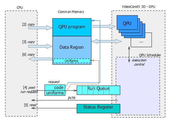
Figure 1. CPU and GPU interactions (direct access to run queue).
Single Run Request that is post into a queue of QPU Scheduler consists only of two items:
(a) address of QPU program and
(b) address of so-called uniforms.
This interface to QPU seems to be 'narrow' but in fact is general and very universal.
In higher level programming languages, it corresponds to specifying the address of function and pointer to its arguments.
Notice that these addresses will be used by QPU, so they must be specified for QPU address space.
That address space is different from the one used by CPU when it access that memory (e.g. copies QPU program).
Hence, the software is responsible for managing two addresses to each region, but it is not difficult because address spaces
have only another base address.
Address [a] is used by the scheduler for setting up PC register of QPU that is started.
The software has no control where is the common memory located, it cannot obtain the memory from any hardcoded address.
It just request from the system an allocation of memory of specified type and size.
There are two implications of that: (1) QPU program must be relocable, (2) location of data region is also dynamic,
so its address must be passed to QPU as well.
Address [b] points to uniforms. From semantic point of view the uniforms are input arguments for QPU.
For VideoCoreIV 3D, the uniforms are represented by a table of 32-bit values. The QPU has sequential access
to this table by reading multiple times from specific register designated for that purpose. The values stored in the uniforms may be anything:
32-bit integer parameter, four 8‑bit values packed into 32-bit word, floating point number, pointer, etc.
Interpretation of the uniforms depends on programmer's choice. It is mostly hardcoded in the application and
the program for QPU, of course they must match on both ends.
The uniforms are also convenient way to distinguish QPU cores between each other. Because the uniforms are specified per QPU,
it is enough to put qpu number there. This differentiation is important because the QPU cores often execute the same program,
but need to work on different part of input data (in this way paralley calculation is implemented).
Data exchange interfaces between CPU and GPU
Broadcom VideoCoreIV 3D provides three ways for data exchange with CPU:
- the uniforms (sequential read only by QPU),
- via Texture and Memory Lookup Unit (read only by QPU)
- via Vertex Pipe Memory exchanged by DMA (read and write access)
The uniforms are convenient for passing arguments and small number of data (e.g. some configurations,
parametrization of algorithm, location of data regions, qpu number etc.). The access to uniforms is sequential and
consists in repeated reading of designated register - unif (see example below in figure 2).
The application on CPU is responsible for preparation the correct image of uniforms (its order and
types). The format is usually hardcoded and specific for each QPU program.
If there are pointers they must be specified in QPU address space.
        mov r_filter, unif     # read address of filter data
        mov r_qpu_number, unif # read number of all QPU used
        mov r_qpu_id,  unif    # read QPU number (QPUid)
        mov r_counter, unif    # read number of input data blocks
        mov r_in_data, unif    # read address of input data buffer
        mov r_out_data, unif   # read address of output data buffer
Figure 2. Example of uniforms usage.
Texture and Memory Lookup Unit is good for access data that
need to be read in random way or treated like a table where its items are selected by an index.
Vertex Pipe Memory is a local memory shared for all QPUs. It can be loaded or stored from/to the common memory region via DMA.
This type of memory has read and write type of access from QPU perspective, so it can be used
for input as well as output data channel. It may exchange larger chunks of data.
Using Vertex Pipe Memory, Vertex Cache Manager and DMA, VPM DMA Writer
Vertex Pipe Memory (VPM) is a kind of local memory that is common for all QPUs.
It is organized as two-dimensional array: 64 rows x 16 columns of 32-bit values (with total size 4KB).
This unit is well fitted to image processing where data is organized in lines. It is possible to access
scattered data in horizontal or vertical way, elements may be even packed in one 32-bit word.
There is also configurable autoincrement functionality (see strade term in chip manual).
The input data is loaded into VPM by another unit - Vertex Cache Manager & DMA (VCM & VCD). After that QPU can
read the data from VPM, process and write it back. Notice that QPU does it in SIMD16 way.
Finally, contents of VPM is stored back into the common memory by VPM DMA Writer (VDW). All units that
are responsible for DMA data transfer from and to VPM may be understood as one virtual module (later refered as VCD). This is manifested
in configuration and usage, that are described below.
Two VPM interfaces on both ends, i.e. to the common memory and to QPU cores, are separately configured. The configuration is performed by QPU
and is little bit confusing. This is because the configuration is done by writting values only to two registers
from QPU address space.
When configuring read or write, ra49 and rb49 registers need to be written correspondingly. Bit 31 of written value
selects the unit (VCD/VPM), the rest of bits contains register selection in the unit and configured fields (refer to table below).
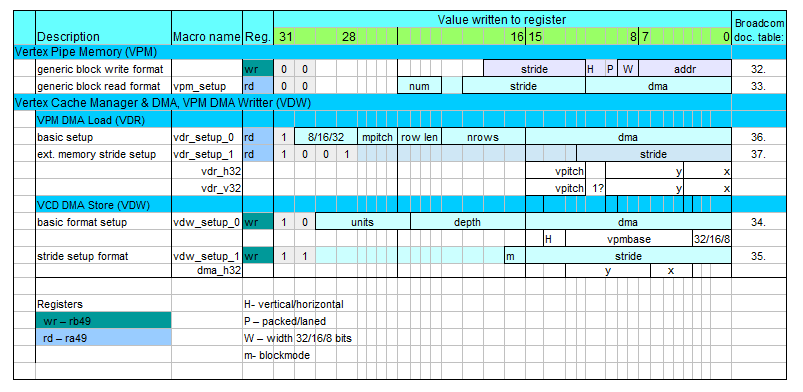
Figure 3. VPM and VCD configuration registers and macros.
The last column of the table contains references to Broadcom Manual - number of table in documentation with detailed description
of the register fields.
For a programmer doing a configuration it is much easier by using already defined macros than calculate register values.
The macros names are provided in the table and their source code is located in example of QPU code in hello_fft (see links at bottom of page).
Besides the configuration there are two more items necessary for working with VCD. The first is setting
the memory address where the data is loaded from/ stored to. For this purpose registers: ra50 (vpm_add_ld) and
rb50 (vpm_add_st) should be used correspondingly. Writting to these registers initiates DMA transfer, so do it after
all setup settings.
The second item is synchronisation - the QPU needs to be notified where data transfer is complete.
Otherwise QPU would read memory that were not loaded yet or overwrite the one that were not fully pushed out
to the common memory.
Reading register ra50 (vpm_wait_ld) or rb50 (vpm_wait_st) holds the QPU until the end of the transfer.
        mov vw_setup, vdw_setup_0(64, 16, dma_h32( 0,0)) # setup DMA write (VPM->SDRAM by VCM&VCD)
        mov vw_setup, vdw_setup_1(0)                     # setup extra stride=0
        mov vw_addr, dbg_rfile_dump                      # set write address and start transfer
        mov -, vw_wait                                   # wait for complete the transfer
Figure 4. Example of VCD write (vw_setup, vw_addr,
vw_wait are QPU closely coupled hardware registers).
Texture and Memory Loookup Unit (TMU)
TMU was originally designed to provide texture mapping. From QPU perspective this unit is read only - it allows only an access to input data.
Nevertheless, it is very useful for GPGPU programming. It provides a way of selective reading the data, where
the access is performed by data indexes. Like QPU core the TMU unit works in SIMD16 way, so it also reads 16 elements at once.
In order to read vector of 16 elements (see example below) a register should be prepared to contain 16 indexes, next
the values need to be multiplied by 4, and finally base address should be added. The resulting value
should be written into tmu#_s register. In next instruction signal to TMU for load must be raised and
after that TMU puts the result in r4 accumulator, so it can be moved to any register.
1        add t0s, r_base_addr, r_indexes        # calculate address and write to tmu#_s
2        ldtmu0                                 # signal load tmu
3        mov r_dst, r4                          # receive value from TMU by reading r4
Figure 5. Example of TMU read.
Note:
when elements contain exact indexes, i.e. without x4 multiplication, the TMU will load into consecutive four elements
the same value corresponding to 4-bytes aligned address. This may be useful for repeated loading the values into quads
instead of into elements.
There are two TMUs for each slice: tmu0 and tmu1. They are shared between four QPU cores located in that slice
(see VideoCoreIV 3D architecture), but fortunately each core has separated queue for its requests.
Althrough queue is deep for 8 entries when using s-coorditate,
only 4 are reliable - this was observed by Marcel Muller.
TMUs are equipped with TMU Cache Memory that is 4KB large and is organized in 64 bytes lines. It uses 10 lowest address bits of the loaded address.
How to start QPU program
The example of QPU programming hello_fft presents two methods of starting QPU programs,
it can be done by:
- VCIO driver that envelopes access to mailbox or
- direct access to the QPU Sheduler Queue.
For both methods VCIO driver is necessary, the application can communicate with it via character device /dev/vcio,
sending messages by ioctl(). The driver allocates the common (shared) memory mentioned at the top of
this page. It can be also useful for execution of QPU programs. Refer to mailbox.c file in the example for more details.
The example hello_fft uses both methods, selecting the one on the basis of expected calculation time.
For short time the direct method is used, while for long time the method via mailbox.
Hence, it can be concluded that method with mailbox has some overhead, necessary for swithing context
to kernel, etc.
The direct method consists in the access to the QPU Scheduler Queue by writing to two registers:
V3D_SRQUA - uniforms address,
V3D_SRQPC - QPU code address (must be written after corresponding uniforms).
Be sure that these addresses are in QPU address space.
The above two writes should be repeated for each instance of QPU program.
Complete of all programs can be detected by testing QPURQCC field in V3D_SRQCS register, where number of completed
programs is incrementally counted. The counter can be cleared before the first program request.
Using direct method often waits in busy waiting mode.
Links
[1] Broadcom VideoCore IV 3D, Architecture Reference Guide - manufacturer's documentation of VideoCore
[2] Addendum to the Broadcom VideoCore IV documentation, Marcel Muller
[3] hello_fft QPU programming example
https://github.com/raspberrypi/firmware/tree/master/opt/vc/src/hello_pi/hello_fft
It is also located in preparred raspbian images in /opt/vc/src/hello_pi/hello_fft.
|

|
