More about ELESOFTROM Company

ELESOFTROM Company is specializing in firmware development and fixing for embedded systems.

We have more than 10-years of experience in that area.

In developed tasks and projects we value reliability and effectivness of the firmware.

Fixing the Software for Emebedded Systems

Software for Microcontrollers


Home page

Full offer

Experience

About company

Contact


DioneOS - RTOS for embedded devices

ELESOFTROM developed RTOS for ARM Cortex-M3 and msp430.

The system is optimized for short execution time, having short switching time between threads.
The system provides elements (e.g. semaphores, mutexes, timers, queues etc.) used for building multi-threaded firmware.

Cortex version has full tests coverage and was tested by automatic testing framework.

Read more:

DioneOS home page

Reliability

Performance

DioneOS documentation

Tutorials about DioneOS


^ Blog index    << System on Chip Broadcom BCM283x in Raspberry Pi    >> Broadcom VideoCoreIV 3D, Basics of Programming

Broadcom VideoCoreIV 3D, Architecture from GPGPU Perspective

2017-12-18   Piotr Romaniuk, Ph.D.

Contents

Architecure of VideoCore 3D
Quad Processing Unit (QPU) - data model
QPU Architecture
QPU Registers
Closely coupled hardware
QPU Instructions
Main limitations of instructions
Links

Architecture of VideoCore 3D
This description provides a general view of VideoCoreIV 3D architecture. The description ilustrates the core from a perspective of graphic processor programmer. Some units were ommitted other simplified just to provide enough information for general programming. More details can be found in Broadcom documentation of the chip (see below (1) in links section).


Figure 1. Simplified architecture of VideoCoreIV-3D.

Central processing part of the core consists of multiple Quad Processing Units (QPU). They are grouped in slices (four QPU in one slice) and equipped with common resources:

  • Instruction Cache (ICache) - cache memory for instructions for all QPU processors in the slice,
  • Uniforms cache - cache memory for arguments (uniforms) that are passed to QPU on the start of execution
  • Texture and Memory Lookup Unit (TMU) - provides textures data; it is convenient for accessing data by indexes
  • Special Functions Unit (SFU) - calculates mathematical functions: 1/x, 1/sqrt(x), log(x), exp(x)

VideoCore 3D contains local shared memory (Vertex Pipe Memory) common for all QPUs. This memory is storage for larger fragment of data and its content is exchanged by DMA with main CPU memory regions. Data can be loaded in parts that corresponds to images structure (i.e columns and rows). Once configured VPM, serves as source or sink of serialized data. Nevertheless, VPM can be reconfigured before bunch of reads or writes (or even signle access) giving the option for flexible access to this memory.
Please notice, that two interfaces are configured: (1) access to VPM by QPU, (2) translation VPM to main memory. Each of them can make some change of data organization (e.g. writing in rows or columns, offset or extra skip to next line).

Quad Processing Unit (QPU) - data model
QPU is SIMD architecture (Single Instruction, Multiple Data), this means that one instruction operates on vector of elements. When looking from programmer's point of view it processes vector of 16 elements each 32bits long. If physical structure is taken into account, QPU processes only 4-element vector (quad). By repeating the instruction 4 times for consecutive quads in 16-element vector, it provides virtual SIMD-16.


Figure 2. Data length for QPU.

Single element is always 32-bit long but may represent different types of data:

  • float - floating point value,
  • int32 - integer 32-bit value,
  • 2x int16 - two integer 16-bit values (packed), consecutive parts are named a, b
  • 4x int8 - four integer 8-bit values (packed) - named a, b, c, d

QPU Architecture
Quad Processing Unit consists of multiple registers (most of them can store 16-element vector) and SIMD16 dual-issue ALU. Some registers are equipped with pack/unpack block. This feature, together with ftoi and itof instructions, provides conversions between various formats.
Hardware parts that are closely coupled (e.g VPM, TMU, SFU) are visible for the QPU in registers' address space. Through this window the QPU transfers data to the hardware, checks its state and setups its configuration. Some addresses (e.g. vpm_wait_ld) provide waiting functionality, reading that enters QPU into stall stage until the hardware completes the operation (e.g. dma transfer). Writing to another address, like tmu0_s, triggers the hardware to do something, here to read data that corresponds to (s,t) coordinates by Texture and Memory Lookup Unit .


Figure 3. Architecture of Quad Processing Unit.

QPU Registers
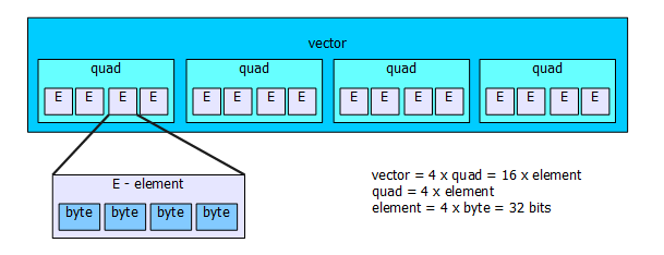
QPU constains a few accumulators and two large files of registers. Each register can keep the vector of elements, so is adapted to SIMD operations. There are 4 accumulators available for general use and 2 special function one. There are 32 registers in each register file, and files are designated by file-A and file-B. All registers in these two files form a local memory that is available per each QPU.


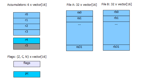
Figure 4. Registers of QPU.

Accumulators and registers from the files differ by:

  • lenght of a data path in QPU pipeline, hence for accumulators result is available for next instruction,
  • flexibility in access in one instruction - there are some constraints on using registers from files
  • vector element rotation can be only performed on accumulators
  • number of accumulators is small

Because of these properties file registers are good for storing variables and configurations for further use, while accumulators should be heavily used in calculations. When the result is obtained it can be stored in the file register. One can tell that the accumulators hold partial results and the file registers have assigned meaning for whole program (like global variables in higher level programming language).

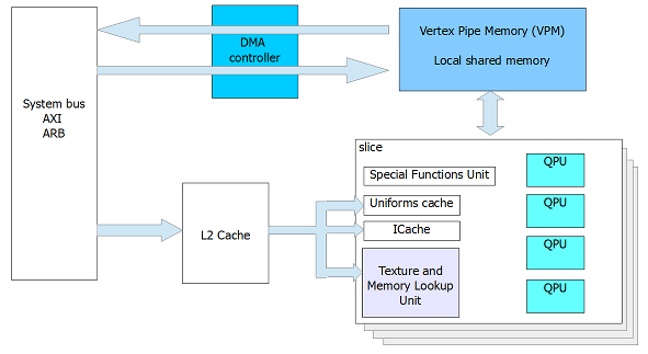
Closely Coupled Hardware
QPU can control hardware that is around it (like: Vertex Pipe Memory, DMA, Texture and Memory Lookup Unit, Special Functions Unit, etc.). These units are accesible via address space of the register files (addresses over 31 are used for this purpose). They act like registers, so regular instructions can operate on them.


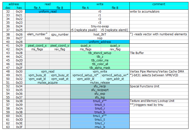
Figure 5. Address space used for access to closely coupled hardware.

QPU Instructions
QPU has 64-bit instruction format (each instruction has this size). There is small number of instruction types but due to size of the processor word they are flexible. The types of instructions are:

  • ALU instructions,
  • load instructions
  • branch instructions
  • synchronization instructions (semaphores)

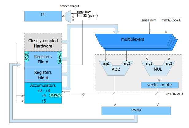
Instructions control the dual-issue ALU that can execute two operations in parallel. One path is responsible for addition operation, while in second one multiplication and vector rotation are performed.
The processor has an instruction pipeline, that is not flushed when branch is executed, hence in examplar source code a strange sequence of instructions can be found. After branch instruction there are three extra, unexpected lines:

1	:entry
2		brr -, r:loop1
3		nop	   ; ldtmu0
4		mov r0, r4 ; ldtmu0
5		mov r1,r4

It means that these three lines (3,4,5) will be executed after branch is taken but before first instruction at the branch target. This happens because they remains in the pipeline when branch is executed.

Details of QPU instructions can be found in VideoCore IV 3D manufacturer's documentation (see (1) in links below). Be sure to read addendum (see (2) in links below) where Marcel Muller, the author of videocore macroassembler explains some specific details of instructions, issues and undocumented features.

Main limitations of instructions
Due to the QPU architecture following limitations may be observed:

  • the result written into file register is not available for next instruction,
  • one instruction cannot use more than one argument from the same register file
  • small immediate cannot be used together with register from file B
  • vector rotation must be performed on accumulator
  • the accumulator that is rotation performed on must not be written in previous instruction
  • packed formats are supported only by registers from file A and accumulator r4
  • there is no hadware stack, selected file register should be used as link register (like in ARM architecture)
  • if results from two parts of ALU (add and mul) are both file registers, they should be in different files

Links

[1] Broadcom VideoCore IV 3D, Architecture Reference Guide - manufacturer's documentation of VideoCore
[2] Addendum to the Broadcom VideoCore IV documentation, Marcel Muller
[3] VideoCore Instructions by Marcel Muller